The Numerical Control Cutting Process Of Thread

It is very important for users to use indexable thread turning tool for threading in CNC lathes and machining centers. The correct and reasonable selection of thread cutting technology is very important.
The thread cutting process depends on the structure of the machined parts and the CNC machine tool used. Generally speaking, using the right cutting edge to process right-handed threads and using the left cutting edge to process left-handed threads has the advantage of stable support of the blade. Of course, in general, the opposite method can also be applied.
Consistent in order to avoid excessive wear on one side of the blade and shortening of tool life as much as possible.
d2――Pitch diameter A――The blade inclination angle is usually determined by the shim of the indexable thread turning tool. The standard tool is +, but for the internal thread tools with diameters of 16mm and 020mm, there is no shim due to the small space. , So it cannot be processed when the blade inclination is greater than +2°.
The feed method of thread turning is determined by the cutting machine, workpiece material, insert geometry and the pitch of the thread being machined. There are usually the following four feed methods: *Commonly used cutting method, the left and right sides of the turning tool are cut at the same time , The axial cutting component force is offset to some extent, which partially overcomes the phenomenon of turning tool deviation caused by the axial cutting component force. The two sides wear uniformly, which can ensure the clear tooth shape, but there are problems such as poor chip evacuation, poor heat dissipation, and concentrated force. It is suitable for cutting threads with a pitch of less than 1.5mm. D single-side feed cutters feed at an angle with the radial direction. The chips are rolled away from the blade to form strips, which have better heat dissipation. The disadvantage is that the other edge is hardened due to the non-cutting of the friction part. D single-sided infeed direction of 30° angle infeed cutting. The cutting edge cuts on both sides to form rolled chips, smooth chip removal, good heat dissipation, and low thread surface roughness value. Generally speaking, this is the best method for turning stainless steel, alloy steel and carbon steel. About 90% of threaded materials use this method. It is best to use this method for thread processing on a CNC lathe. Generally, a fixed cycle can be called and the programming is simple.
The left and right side feeds alternately cutting, that is, each time the radial feeds, move a certain distance laterally to the left or right, so that only one side of the turning tool participates in the cutting. This method is generally used for general-purpose lathes and thread processing with a medium distance of more than 3mm, and programming on CNC lathes is more complicated.
Thread milling is mainly used for CNC boring and milling machine tools such as machining centers. Generally, small-diameter internal threads (20mm) can be processed by tapping. However, for the processing of large-diameter internal threads and external threads, there are many problems with tapping and sleeve threads. Therefore, medium grain iron cutting is the best processing. means.
Thread milling is different from thread turning plus X. This is because the pattern CNC milling is mainly realized through the three-axis linkage and helical interpolation processing of the machine tool, that is, while the two-axis arc sensitive cutting is processed, the first Three-axis linear feed motion. The axial movement distance is milled. It is a single-edge milling process. Therefore, the best way to feed is to use the radial direct feed cutting method, so that the two cutting edges cut at the same time, and the force is more uniform. , Which can ensure the accuracy of the thread, and the CNC programming is relatively simple.
Second, the choice of thread turning and milling cutting The choice of thread cutting parameters (cutting speed, back-cutting amount, number of passes) is determined by the material of the tool and the part. The cutting speed of thread turning is generally 25% ~50% lower than that of ordinary turning. The selection of the amount of backing of the thread and the number of passes are also particularly important. Whether the D value is correct or not is directly related to whether the medium pattern is qualified or not. The amount directly affects the size of the cutting force. The amount of the back of the centipede needs to follow the principle of decreasing, that is, the amount of the back of the back of the knife must be less than the amount of the previous one, and the value of the minimum back of the knife shall not be less than. 5 stomach. The following two tables provide the metric internal and external media pattern backing values. This table is also suitable for thread milling.
Table 1 ISO Metric Pattern Back Knife Setting Value (External Thread) (mm) Pitch Back Knife Cutting Times Flavored Back Knife Quantity Cutting Times Table 2 ISO Metric Pattern Back Knife Setting Value (Internal Thread) Cadmium Back Knife Cutting Times For CNC boring and milling machine tools, although thread milling is realized by three-axis linkage spiral interpolation processing, which is different from thread turning, the choice of cutting quantity can still be used by turning media. The relevant cutting parameters of the pattern. Because the thread milling is made by single-edge cutting, the cutting speed should be half that of turning, and the amount of back-cutting can still be selected according to turning.
3. Thread turning and milling CNC program preparation For CNC lathes, the general standard thread turning programming instructions are G33 (fixed pitch cutting), G34 (variable pitch butterfly cutting with increasing pitch), G35 (variable pitch with decreasing pitch Thread cutting). The medium distance is specified by / and person ruler, where K /, A: correspond to the X and Z axes respectively. However, general CNC systems and machine tool manufacturers provide thread turning canned cycles for users to use, and only need to input the necessary parameters. H. When processing special butterfly patterns, it is necessary to use the G command and the programming method of calculating the coordinate points by yourself.
The programming of thread milling processing is different from that of CNC turning. G02 and G03 arc interpolation commands are mainly used, that is, the third axis linear interpolation is added while the two-axis arc interpolation is added to form a spiral interpolation movement. The following is the ordinary internal thread M30X 2, deep 14mm CNC milling processing program , Take the knife back to 1.2mm, adopt the radial direct cutting method.
F200 takes edge compensation, radial feed to the position of the back-grabbing tool. In centuries cutting, it is often due to the correctness of the selection of tools (including inserts, shim and arbor, etc.), feed method, cutting amount, etc. Affects the processing quality of centipede, such as: thread surface has shock marks, surface roughness value is 篼. This may be due to excessive extension of parts or tools, poor rigidity, excessive cutting of the center of the tool, and incorrect selection of cutting amount, blades, and stings And other factors. It is possible to increase or decrease the cutting speed, shorten the outer elongation of the tool, adjust the center height or feed method, adopt side feed or radial feed, adequate cooling, increase the number of passes and other solutions.
Fast tool wear and short tool life are caused by too fast cutting speed, insufficient cooling, too many cutting times, and wrong blade brand. It can be used to reduce the cutting speed, fully cooling, reduce the number of cutting, choose the hardness of the wear-resistant blade D with good toughness, change the cutting angle, increase the cooling, increase the cutting speed, reduce the amount of back knife, and adjust the center frame.
In the traditional processing process, the bottom surface is scribed and planed first, and then processed on the T611 boring machine. During processing, each piece needs to be corrected, which is troublesome in clamping, time-consuming and labor-intensive, and low efficiency.
The processing capacity is insufficient. Therefore, we designed a special tooling fixture for turning and boring to produce a bearing bracket (H7rr35 with a center height of 257s), which is the main size of the workpiece. Based on this, the design of tooling fixtures is as shown. The jig is used on the CW6263 lathe.
The clamp is composed of a main body 3 and a three-jaw self-centering chuck 4. Remove one claw of the three-jaw self-centering chuck. The left end of the main body 3 is connected with the chuck and fastened with bolt 1. The A side table is placed on the positioning surface of the bearing bracket. The main body has two notches for the free movement of the claws. s First, ensure the center of the bearing bracket 5, and then use the three-claw self-selection due to improper selection, to change the feed method and cut corners.
The built-up edge on the cutting edge increases the cutting speed and increases the cooling. The coated carbide inserts are used for cutting with an improved side feed.
Excessive plastic deformation of the tool is due to poor cooling, too high cutting speed, the wrong blade grade, and the amount of back-grabbing each time is too large. Should reduce the amount of back-grabbing, increase cooling, reduce cutting speed, increase cutting times, use high hardness, wear-resistant hard alloy or Xu layer blades.
If there is a burr on the thread, the cutting speed should be increased. Use the automatic centering principle of the cutting centering chuck 4 to clamp the workpiece for processing.
Then tighten the chuck to clamp the workpiece.
The use of car instead of collision fully meets the design requirements of the bearing bracket, guarantees dimensional accuracy and position accuracy, and saves workpiece scribing and correction, guarantees quality, and improves work efficiency by 1.8 times compared with boring.
Bearing brackets with different center heights can be adjusted by adding pad irons, but they need to be fastened by bolts.
Before use, balance adjustment is required to avoid the influence of centrifugal force on the quality of the workpiece and the pressure plate on the equipment.
Please keep the source and address of this article for reprinting:The Numerical Control Cutting Process Of Thread
Minghe Die Casting Company are dedicated to manufacture and provide quality and high performance Casting Parts(metal die casting parts range mainly include Thin-Wall Die Casting,Hot Chamber Die Casting,Cold Chamber Die Casting),Round Service(Die Casting Service,Cnc Machining,Mold Making,Surface Treatment).Any custom Aluminum die casting, magnesium or Zamak/zinc die casting and other castings requirements are welcome to contact us.
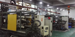
Under the control of ISO9001 and TS 16949,All processes are carried out through hundreds of advanced die casting machines, 5-axis machines, and other facilities, ranging from blasters to Ultra Sonic washing machines.Minghe not only has advanced equipment but also have professional team of experienced engineers,operators and inspectors to make the customer’s design come true.
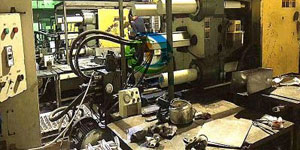
Contract manufacturer of die castings. Capabilities include cold chamber aluminum die casting parts from 0.15 lbs. to 6 lbs., quick change set up, and machining. Value-added services include polishing, vibrating, deburring, shot blasting, painting, plating, coating, assembly, and tooling. Materials worked with include alloys such as 360, 380, 383, and 413.
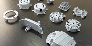
Zinc die casting design assistance/concurrent engineering services. Custom manufacturer of precision zinc die castings. Miniature castings, high pressure die castings, multi-slide mold castings, conventional mold castings, unit die and independent die castings and cavity sealed castings can be manufactured. Castings can be manufactured in lengths and widths up to 24 in. in +/-0.0005 in. tolerance.
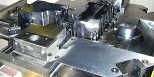
ISO 9001: 2015 certified manufacturer of die cast magnesium, Capabilities include high-pressure magnesium die casting up to 200 ton hot chamber & 3000 ton cold chamber, tooling design, polishing, molding, machining, powder & liquid painting, full QA with CMM capabilities, assembly, packaging & delivery.
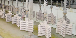
ITAF16949 certified. Additional Casting Service Include investment casting,sand casting,Gravity Casting, Lost Foam Casting,Centrifugal Casting,Vacuum Casting,Permanent Mold Casting,.Capabilities include EDI, engineering assistance, solid modeling and secondary processing.
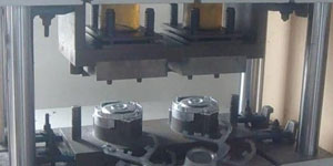
Casting Industries Parts Case Studies for: Cars, Bikes, Aircraft, Musical instruments, Watercraft, Optical devices, Sensors, Models, Electronic devices, Enclosures, Clocks, Machinery, Engines, Furniture, Jewelry, Jigs, Telecom, Lighting, Medical devices, Photographic devices, Robots, Sculptures, Sound equipment, Sporting equipment, Tooling, Toys and more.
What Can we help you do next?
∇ Go To Homepage For Die Casting China
→Casting Parts-Find out what we have done.
→Ralated Tips About Die Casting Services
By Minghe Die Casting Manufacturer |Categories: Helpful Articles |Material Tags: Aluminum Casting, Zinc Casting, Magnesium Casting, Titanium Casting, Stainless Steel Casting, Brass Casting,Bronze Casting,Casting Video,Company History,Aluminum Die Casting |Comments Off

