Three Reasons For Melt Leakage During Mold Production
Compared with ordinary runner molds, the gating system in the hot runner mold is always at a high temperature during use, and the plastic melt is prone to leak at the joints of the parts of the hot runner system under the action of high temperature and high pressure. Melt leakage will not only affect the quality of plastic parts, but also severely damage the mold, resulting in failure to produce. There are two main leaking parts of the hot runner mold, one is the end face of the runner on the runner plate, and the other is the junction surface of the runner plate and the nozzle (including the gate nozzle and the main runner nozzle). There are many reasons for melt leakage, which can be summarized into three aspects: improper operation, assembly process, and unreasonable sealing design. This article introduces the causes of melt leakage and precautionary measures.

Melt leakage caused by process factors
Improper operation technology is one of the main reasons for melt leakage during mold production. In order to compensate for the thermal expansion of the parts of the hot runner system, there is often a certain cold gap between the parts when designing and assembling the mold. Only under the specified operating temperature, the thermal expansion of the parts can completely eliminate the cold gap and achieve sealing and leakage prevention. Melt leakage caused by improper operation mainly occurs in the following situations:
- Melt leakage caused by improper system heating process or uneven temperature control. During the heating process, if the nozzle heating rate is higher than the heating rate of the hot runner plate, the axial thermal expansion of the system parts will limit the transverse thermal expansion of the hot runner plate, causing the hot runner plate to deform and cause melt leakage. The uneven temperature of the parts of the gating system will cause uneven expansion of the parts, and will also cause the parts to deform and cause melt leakage.
- Inject in advance when the system does not reach the specified operating temperature. As shown, after the system is heated, the support ring 6, the hot runner plate 5, and the gate nozzle 4 undergo thermal expansion in the axial direction, and the support ring is compressed on the fixed mold mounting plate 3, and a certain amount of heat is generated between the hot runner plate and the nozzle. pressure. If the injection is performed when the specified temperature is not reached, the thermal pressure generated by thermal expansion is not enough to offset the melt pressure, which will cause the nozzle 4 and the hot runner plate 5 to separate and cause melt leakage.
- Melt leakage caused by system heating temperature higher than operating temperature. In this case, due to the excessive thermal expansion, a large thermal pressure will be generated, which will cause the system parts to deform and melt leakage.
On the other hand, when the temperature of the gating system is reduced to the operating temperature, melt leakage will also occur due to the poor adaptability of the thermal nozzle with rigid edges to thermal expansion.
In summary, operating according to the correct steps and process conditions is a prerequisite to avoid melt leakage. The general hot runner mold can be operated according to the following steps:
- Heat the hot runner system to the set temperature. It is generally divided into two steps: The first is a soft start to eliminate the moisture in the heater.
- Heat the mold to the set temperature. Especially for large molds, it is heated before injection and then cooled during injection.
- Heat the barrel of the injection machine to the set temperature.The second step is to heat the system to the set temperature at full load. The nozzle temperature can be heated to 2/3 of the hot runner plate temperature. After the hot runner plate temperature reaches the design temperature, the nozzle temperature is heated to the set temperature.
- For the new or cleaned hot runner system, low-pressure slow injection should be used first.
- If there is no melt leakage after several cycles of injection, the set injection process parameters are used for production.
Sealing design of hot runner system
Thermal expansion compensation of hot runner system
The mold assembled at room temperature will cause the relative position of the parts to change during the thermal expansion of the parts of the hot runner system. In order to compensate for the thermal expansion of the parts, it is necessary to leave a suitable expansion gap, such as the cold gap A and C shown. It is fixed on the fixed template 1 by the center positioning pin 7 and stretches around after being heated. The transverse thermal expansion of the hot runner plate will reduce the gap A between the hot runner plate and the anti-rotation pin 2. If the value A is smaller than the transverse thermal expansion of the hot runner plate in the design, the anti-rotation pin will prevent the transverse extension of the hot runner plate after heating.
It causes the warpage and deformation of the hot runner plate, which makes the seal between the hot runner plate and the nozzle ineffective and causes melt leakage. The axial thermal expansion of the support ring 6, the hot runner plate 5, and the gate nozzle 4 will eliminate the cold gap C. If the cold gap is too large and the axial thermal expansion is insufficient, the melt pressure during injection will cause the gate nozzle 4 and the hot runner The plate 5 is separated and the melt leaks. If the cold gap is too small and the thermal expansion pressure of the system is too large, the system parts will be bent, or the compressive stress will exceed the yield stress of the fixed template, which will cause the support ring to crush the fixed template, thereby limiting the lateral thermal expansion of the hot runner plate and causing the gate Melt leakage occurred between the nozzle and the hot runner plate.
Therefore, when designing the mold, correctly calculating the thermal expansion of the system and leaving a reasonable thermal expansion gap are the prerequisites to prevent melt leakage. The linear thermal expansion of the system can be calculated by the following formula: L=TL (1) The thermal stress caused by the resistance of the thermal expansion of the system is: =EL-CL (2) The pressure of the fixed mold fixed plate is checked by the following formula p(3) where: L Is the linear thermal expansion of the hot runner system, mm; is the linear thermal expansion coefficient of the system parts material; T is the temperature difference between the hot runner system parts and the mold; L is the length of the runner system parts in the expansion direction at room temperature, mm; is the system thermal expansion The thermal stress caused by resistance, MPa; C is the amount of reserved gap, mm; E is the elastic modulus of the system parts, MPa; p is the allowable compressive stress of the fixed mold plate material.
The sealing form of the hot runner system
The plane seal between the hot runner plate and the nozzle is a common sealing form in foreign hot runner systems. After the system is thermally expanded in the axial direction, the support ring is pressed on the fixed mold plate, and a certain thermal pressure is generated at the joint plane of the hot runner plate and the nozzle to offset the melt pressure to seal and prevent leakage. This type of structure cannot guarantee cold sealing, and there is no overheating protection measure. Only under the set temperature conditions can the hot runner plate and the nozzle be sealed. When designing, it is necessary to accurately calculate the thermal expansion and leave a suitable cold gap C.
b. O-shaped sealing ring is used on the joint plane of nozzle and hot runner plate. O-shaped sealing ring is made of stainless steel pipe. When assembling, there is a preload of 2030 steel pipe diameter to prevent melt leakage. This structure is very suitable for low-rigidity hot runner plates and molds.
The elastic connection is adopted, and the spring provides pre-tension to realize the sealing under the cooling state. When overheating, the spring absorbs thermal expansion to prevent system damage and leakage. It is an ideal sealing form.
The gate nozzle is fixed on the hot runner plate by threads, and the nozzle and the sliding pressure ring move with the hot runner plate when the system thermally expands. Since the movement of the nozzle will cause the misalignment of the nozzle runner axis and the gate axis on the fixed template, the lateral thermal expansion should be considered when designing the nozzle position. This type of sealing is suitable for occasions with few injection points and small nozzle spacing.
Hot runner plate assembly process
The assembly accuracy and installation sequence of the hot runner system are directly related to whether the melt leaks. If the nozzle height is inconsistent, the gap between the shortest nozzle and the hot runner plate will cause melt leakage, and the deformation of the hot runner plate caused by the inconsistent height of the support pad and the nozzle height will also cause melt leakage.
The following takes a 1-mold 4-cavity plastic box hot runner mold as an example to illustrate the assembly process of the hot runner plate:
- Tightly fix the mold fixing plate.
- Press the runner block 7 into the hot runner plate 10, install the anti-rotation pin 2 after correcting the direction, and then press the block with the compression screw 3, and use the O-shaped metal sealing ring to prevent the melt from leaking.
- Install the gate nozzle 1 and the supporting pad 15 in the fixed template 14, and check whether the height of all nozzle assembly planes are the same based on the fixed template plane. If they are inconsistent, perform grinding at the minimum value, with a tolerance of 0.01mm .
- Try to install the hot runner plate and check whether the hot runner plate and the anti-rotation pin 2 have necessary clearances A and B in the radial and axial directions.
- Fix the backing plate frame 12 on the fixed template 14 with bolts.
- Based on the upper plane of the backing frame 12, repair all the pressure rings 6 to make them consistent in height and have a gap with the upper plane of the backing frame. C.
- Screw the main runner nozzle 9 into the hot runner plate 10.
Please keep the source and address of this article for reprinting:Three Reasons For Melt Leakage During Mold Production
Minghe Die Casting Company are dedicated to manufacture and provide quality and high performance Casting Parts(metal die casting parts range mainly include Thin-Wall Die Casting,Hot Chamber Die Casting,Cold Chamber Die Casting),Round Service(Die Casting Service,Cnc Machining,Mold Making,Surface Treatment).Any custom Aluminum die casting, magnesium or Zamak/zinc die casting and other castings requirements are welcome to contact us.
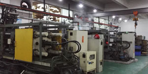
Under the control of ISO9001 and TS 16949,All processes are carried out through hundreds of advanced die casting machines, 5-axis machines, and other facilities, ranging from blasters to Ultra Sonic washing machines.Minghe not only has advanced equipment but also have professional team of experienced engineers,operators and inspectors to make the customer’s design come true.
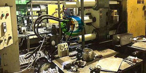
Contract manufacturer of die castings. Capabilities include cold chamber aluminum die casting parts from 0.15 lbs. to 6 lbs., quick change set up, and machining. Value-added services include polishing, vibrating, deburring, shot blasting, painting, plating, coating, assembly, and tooling. Materials worked with include alloys such as 360, 380, 383, and 413.
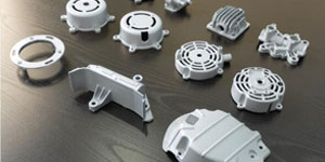
Zinc die casting design assistance/concurrent engineering services. Custom manufacturer of precision zinc die castings. Miniature castings, high pressure die castings, multi-slide mold castings, conventional mold castings, unit die and independent die castings and cavity sealed castings can be manufactured. Castings can be manufactured in lengths and widths up to 24 in. in +/-0.0005 in. tolerance.
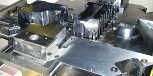
ISO 9001: 2015 certified manufacturer of die cast magnesium, Capabilities include high-pressure magnesium die casting up to 200 ton hot chamber & 3000 ton cold chamber, tooling design, polishing, molding, machining, powder & liquid painting, full QA with CMM capabilities, assembly, packaging & delivery.
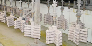
ITAF16949 certified. Additional Casting Service Include investment casting,sand casting,Gravity Casting, Lost Foam Casting,Centrifugal Casting,Vacuum Casting,Permanent Mold Casting,.Capabilities include EDI, engineering assistance, solid modeling and secondary processing.
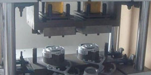
Casting Industries Parts Case Studies for: Cars, Bikes, Aircraft, Musical instruments, Watercraft, Optical devices, Sensors, Models, Electronic devices, Enclosures, Clocks, Machinery, Engines, Furniture, Jewelry, Jigs, Telecom, Lighting, Medical devices, Photographic devices, Robots, Sculptures, Sound equipment, Sporting equipment, Tooling, Toys and more.
What Can we help you do next?
∇ Go To Homepage For Die Casting China
→Casting Parts-Find out what we have done.
→Ralated Tips About Die Casting Services
By Minghe Die Casting Manufacturer |Categories: Helpful Articles |Material Tags: Aluminum Casting, Zinc Casting, Magnesium Casting, Titanium Casting, Stainless Steel Casting, Brass Casting,Bronze Casting,Casting Video,Company History,Aluminum Die Casting |Comments Off

